Industry Portal
Related News
- 00
0000-00
Choosing Joining Technologies for Lightweight Multi-Material Vehicle Structures - 00
0000-00
Vehicle Lightweighting for Automotive Design: Balancing Mass, Safety, and Cost - 00
0000-00
ISO 9001 Requirements for Automotive Exterior Component Suppliers - 00
0000-00
Supplier Capability Evaluation Matrix: Criteria and Weighting for Reliable Sourcing - 00
0000-00
How to Choose SUV Performance Tires for Grip, Load Capacity, and Daily Comfort
Choosing Joining Technologies for Lightweight Multi-Material Vehicle Structures
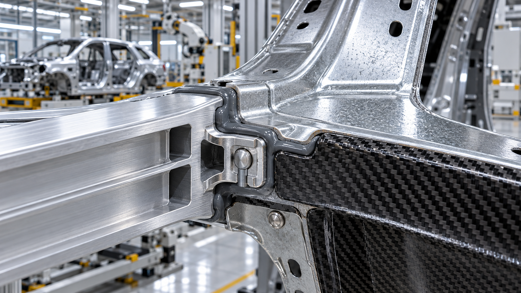
A multi-material body structure can look straightforward on a CAD screen: aluminum extrusion meets stamped steel, a composite reinforcement closes a load path, and a thin-gauge panel reduces mass. The difficulty appears when that interface reaches production. A joint that carries static load may still fail a crash pulse, create a galvanic corrosion path, distort a visible outer panel, or demand a cycle time that the line cannot absorb.
The right choice among vehicle lightweighting joining technologies is therefore not a matter of selecting the strongest standalone process. The practical decision is to define what the joint must do, identify the material and access constraints, then select a primary joining method with any necessary sealing, isolation, or load-sharing feature. Adhesive bonding is often the most versatile foundation for mixed materials; mechanical fasteners add immediate retention and predictable crash behavior; welding remains efficient where compatible metals and access conditions permit. Hybrid joints are frequently the most defensible choice when structural, durability, and production requirements must coexist.
Start with the joint function, not the joining process
Before comparing rivets, welds, screws, or adhesives, separate the functions expected from the interface. A roof frame joint, battery enclosure seam, wheelhouse reinforcement, and cosmetic closure panel may all connect similar material families, yet their governing requirements differ substantially.
A useful early review asks whether the joint must transfer shear, peel, bending moment, impact energy, electrical current, pressure, or merely retain panel position. It should also establish whether the joint lies within a crash load path, faces cyclic vibration, experiences thermal cycling, or remains exposed to road splash. These conditions decide whether local strength, stiffness, fatigue life, sealing performance, or corrosion control should receive priority.
- Crash-critical joints require controlled load transfer, stable failure behavior, and enough retained capacity before an adhesive fully cures or after it ages.
- Stiffness-driven joints, such as large closures or frame interfaces, benefit from continuous bonded areas that distribute load rather than concentrating it at discrete fasteners.
- Sealed enclosures need a joining concept that maintains leak resistance through vibration, temperature change, and service life.
- Visible exterior panels demand low distortion, clean surface quality, and minimal print-through from the joint line.
- Serviceable assemblies may need removable fasteners even when a permanent structural method would offer better mass or cycle-time performance.
This functional definition prevents a common evaluation error: selecting a process because it is proven on one vehicle component and assuming it will behave similarly in another load case.
Map the materials before judging compatibility
Material names alone are not enough. The evaluation should document alloy family, temper, thickness, coating, fiber architecture, resin system, and surface condition. Two aluminum sheets with different tempers may respond differently to forming around a self-piercing rivet. A steel coating can affect electrical resistance, weld quality, and corrosion protection. Fiber-reinforced polymer parts may tolerate distributed adhesive load but crack when a point fastener induces local bearing stress.
Material pairing also determines the likely corrosion and thermal-expansion risks. Direct contact between aluminum and steel can create a galvanic couple when moisture and conductive contamination reach the interface. Carbon-fiber-reinforced polymer deserves particular attention because exposed carbon fibers can be electrically conductive and may accelerate galvanic attack on adjacent metals. Sealants, adhesive layers, coatings, isolating washers, and controlled edge coverage can all form part of the joining system rather than being treated as secondary details.
Thermal movement matters in large assemblies. Aluminum generally changes dimension more than steel under the same temperature excursion, while composite laminates may behave differently by fiber direction. A rigid, short bond line can concentrate thermal stress; a properly selected adhesive with suitable elongation may accommodate relative movement. The relevant question is not whether a material pair can be joined, but whether the joint geometry and process can manage movement over the vehicle’s expected operating environment.
Where the main joining options fit
Adhesive bonding: powerful, but rarely a complete decision by itself
Structural adhesives are central to lightweight construction because they join dissimilar substrates without creating a fusion zone and spread load over a broad area. They can increase torsional stiffness, reduce local stress peaks, damp vibration, and isolate incompatible materials. In a steel-to-aluminum overlap, the adhesive can also limit direct electrolyte access to the interface when edge sealing and process control are adequate.
Its limitations should be evaluated with equal discipline. Bond strength depends on surface chemistry, contamination control, adhesive bead placement, bond-line thickness, clamping, cure profile, and joint design. A bonded lap joint can perform well in shear but may be vulnerable when geometry introduces peel. Production teams also need a plan for uncured-part handling, open time, cure confirmation, and rework. A joint that has excellent final properties may still require temporary retention during body framing or before oven cure.
For this reason, adhesive is frequently paired with self-piercing rivets, flow-drill screws, spot welds, or clinches. The mechanical element locates the parts and provides immediate handling strength, while the cured adhesive distributes service loads and helps seal the interface. The combination must be validated as one system: a fastener can alter adhesive flow, create local stress concentration, or puncture a corrosion barrier if its placement is poorly controlled.
Mechanical fastening: decide from stack-up and access
Mechanical joining is especially useful when melting is unsuitable, when a part cannot tolerate high heat, or when curing alone does not fit the assembly sequence. Self-piercing rivets are commonly considered for sheet stack-ups because installation does not require a pre-drilled hole and can be performed quickly with controlled force. Their feasibility depends on the complete stack, not just the top sheet. Thickness changes, hard reinforcements, cast nodes, adhesive beads, and material temper can all change how the rivet flares into the lower layer.
Flow-drill screws can address areas where only one side is accessible. They can work well in closed profiles and can simplify certain assembly sequences, but the installation process creates localized heat and forms threads or material displacement within the stack. The selected screw, pilot strategy where applicable, tightening control, and coating system must be assessed together. In moisture-exposed locations, the screw head and interface may require sealing to avoid a water path.
Clinching can be attractive where material and geometry allow it, particularly for thin sheet assemblies. It avoids an added fastener, but the local interlock has clear limits in thick, brittle, high-strength, or highly dissimilar stacks. It should not be selected simply because it is low-cost at the point of installation; the tooling reach, flange design, and required joint count can dominate its practical value.
Do not treat welding as a default metal solution
Welding remains highly effective for compatible metallic structures, especially where the existing line architecture, joint access, and material metallurgy support it. Resistance spot welding can be efficient for conventional steel assemblies, while laser or arc processes may suit specific continuous seams. Yet lightweight design often introduces aluminum, coated steels, castings, and composites that make direct fusion more difficult or undesirable.
The main concern is not only whether a weld can be made. Heat input may alter local material properties, damage coatings, increase distortion, create porosity, or complicate dimensional control near a visible surface. Dissimilar metal welding can also create brittle intermetallic layers or inconsistent joint performance unless the process and materials are specifically engineered for that pairing. Where a welded steel subassembly later attaches to aluminum or composite parts, it may be more efficient to preserve welding within the compatible subassembly and use a different joining method at the material transition.
Use joint geometry to reduce risk before selecting equipment
A weak geometry cannot be rescued reliably by changing fastener brand, adhesive grade, or weld schedule. The design review should look first at overlap length, flange width, edge distance, material stack order, access for tooling, and the direction of applied load. A joint that loads an adhesive mainly in shear is generally more favorable than one that repeatedly opens in peel. A riveted connection needs enough surrounding material to resist tearing and enough lower-sheet thickness to form its designed interlock.
Drainage and edge treatment are equally important in exterior and underbody areas. Trapped water at a lap joint can undermine otherwise sound corrosion protection. Narrow gaps may be difficult to seal consistently, while excessive gaps can consume adhesive unevenly or interfere with fastener setting. Design teams should identify where water, salt, cleaning fluids, or thermal exposure can reach the joint before finalizing process selection.
Evaluate the manufacturing system, not only coupon results
Coupon testing is necessary, but it does not represent a production body structure on its own. A process should be reviewed across part variation, fixture repeatability, robot reach, cycle time, tool maintenance, consumable supply, inspection method, and rework path. A joining concept that is robust in a laboratory may be fragile when panel tolerances shift, adhesive viscosity changes within its working window, or a tool reaches the joint at an unfavorable angle.
Quality verification must be planned early. For adhesive bonding, this can include bead presence monitoring, applied-volume control, surface-cleanliness discipline, gap verification, and cure-process traceability. Riveted and screwed joints require confirmation of seating, force or torque signatures where relevant, tooling condition, and visual or sectional validation during process development. Welded joints need parameter monitoring and a method for detecting instability caused by electrode condition, fit-up, coating variation, or thermal effects.
Destructive validation should reflect the actual joint environment: static strength alone is insufficient for components exposed to fatigue, impact, corrosion, thermal cycling, or vibration. The test plan should include representative material condition, coating state, adhesive cure condition, production-intent geometry, and realistic load direction. A clean coupon failure can conceal an edge-sealing issue or a local peel condition that appears only in the assembled structure.
A practical selection sequence
- Define the joint’s load path, safety relevance, sealing requirement, serviceability, and visible-surface constraints.
- Record the full material stack-up, including coatings, thickness tolerances, temper, adhesive presence, and likely environmental exposure.
- Screen out methods that cannot meet access, heat-input, or material-compatibility limits.
- Develop feasible joint geometries before comparing equipment or cycle times; include corrosion isolation and drainage features at this stage.
- Assess whether adhesive alone can meet handling and crash requirements, or whether a mechanical or welded companion process is needed.
- Run production-representative trials that examine installation quality, dimensional repeatability, inspection capability, and failure mode rather than peak load alone.
- Approve the process only after durability and corrosion assessments confirm that the joint system remains stable beyond the initial assembly condition.
The most reliable lightweight joints are usually those in which material selection, geometry, corrosion protection, and assembly sequence were decided together. Choosing a joining method after the part interface is already fixed often leads to added reinforcement, extra fasteners, difficult sealing operations, or compromised cycle time—each of which can erase part of the original mass-saving objective.