
Industry Portal
Related News
- 00
0000-00
Precision Forging for Aluminum Wheels: Alloy Selection and Fatigue Performance - 00
0000-00
NEV Industry Standards in China: Which Battery Safety Tests Are Required? - 00
0000-00
Automotive Exterior Lighting Systems: Lamp Types, Functions, and Placement - 00
0000-00
Choosing an Electric SUV Sunroof: Key Fit, Safety, and Weather-Sealing Factors - 00
0000-00
Pop-Up Automotive Sunroof Systems: Key Design Factors for Vehicle Integration
Headlight Thermal Management Standards: Testing LED Heat Dissipation and Reliability
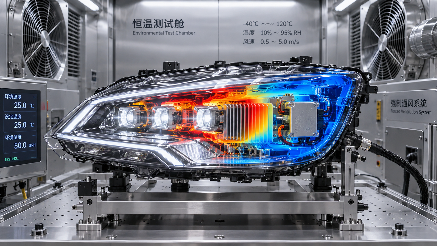
An LED headlamp can pass an initial photometric check and still fail in service when heat accumulates inside the housing. The beam may gradually lose intensity after a long night drive, a driver may reduce current to protect itself, color may drift between modules, or a polymer optic may show early haze or distortion. These are not separate problems. They are often different symptoms of an insufficiently verified thermal system.
The central judgment behind headlight thermal management standards is that an assembly must maintain safe temperatures and stable optical output across its intended electrical, ambient, airflow, vibration, and aging conditions. A single temperature reading at the heat sink is not enough. A credible assessment traces heat from the LED junction through the board, thermal interface, housing, and surrounding air, then confirms that this heat path remains effective after environmental exposure and repeated operation.
Start by defining what “acceptable temperature” means for the assembly
Thermal limits should not be treated as one universal number. An LED package, solder joint, driver IC, connector, optical lens, sealing gasket, and plastic housing can each have different temperature capabilities and different failure mechanisms. The relevant limit is therefore not simply the hottest point found during a test. It is the temperature of each critical component relative to its approved operating range, measured or estimated using a method that can be repeated.
For an LED module, junction temperature is usually the most important parameter because it directly affects luminous flux, chromatic stability, electrical behavior, and long-term degradation. Yet the junction is not usually accessible to a probe in a completed lamp. Assessors commonly rely on a validated relationship between electrical characteristics and junction temperature, or use calibrated thermal models supported by measurements at defined reference points. Surface temperature alone can be useful for comparison, but it should not be presented as proof of junction compliance without correlation.
The assessment plan should identify the thermal limits that actually govern release decisions:
- maximum permitted LED junction temperature during steady operation and thermal transients;
- temperature limits for the LED driver, current-control components, and protection circuitry;
- material limits for lenses, reflectors, light guides, coatings, adhesives, seals, and wire insulation;
- allowable temperature at connectors and terminals, especially where contact resistance may rise over time;
- temperature thresholds at which dimming, current derating, warning functions, or shutdown are expected to activate.
These limits should come from the applicable component specifications, vehicle requirements, and regulatory or approval framework. A thermal test cannot compensate for an undefined requirement. Before testing begins, confirm whether the lamp is expected to operate at full output continuously, whether adaptive functions create high-duty operating modes, and whether protective derating is allowed without compromising required beam performance.
The thermal path must be evaluated as a system, not as a heat sink
A common review error is to focus on the visible aluminum heat sink while overlooking the interfaces around it. In a typical LED headlamp, heat travels from the semiconductor junction to the package, through solder joints into a metal-core board or substrate, across a thermal interface, into a structural carrier or heat sink, and finally to the surrounding air. Every transition adds thermal resistance. A small gap, uneven fastener load, excessive interface thickness, warped board, or poorly controlled adhesive bead can have a larger effect than a modest change in heat-sink fin area.
The housing also changes the result. A lamp mounted behind a fascia, near a radiator support, or in a tightly packaged front-end module may see restricted airflow and heat radiated from nearby systems. An assembly that remains cool on an open bench can behave differently once installed in its representative vehicle position. Evaluation should therefore distinguish between component-level characterization and vehicle-representative thermal validation.
Questions that reveal weak assumptions early
- Is the module tested in its final mounting orientation, including brackets and sealing features that alter heat flow?
- Does the chosen power mode represent the highest sustained electrical load, rather than a short activation event?
- Are cooling fans, shutters, adaptive optics, or moving mechanisms operating in the condition that creates the highest internal heat load?
- Has the effect of solar loading, under-hood heat soak, and reduced vehicle-speed airflow been considered where required?
- Are thermal interface materials controlled for thickness, compression, placement, and aging?
These questions matter because thermal margins can disappear after small production variations. A design that works only with ideal contact pressure or a perfectly placed pad is not robust enough for normal manufacturing spread.
Use test conditions that reproduce the thermal stress, not merely the laboratory setup
Thermal validation generally needs both steady-state and transient testing. Steady-state testing establishes the temperatures reached after the lamp has stabilized at a defined ambient condition, electrical input, and airflow state. It is essential for identifying the limiting operating point, but it does not show how the system reacts to rapid changes.
Transient conditions are especially relevant for smart lighting assemblies. A cold lamp may start at high current, then experience a rising internal temperature as the vehicle remains stationary. Conversely, a lamp that has been exposed to high ambient temperature may be switched on during a heat-soaked condition. The driver’s response curve, sensor placement, and thermal mass all influence whether the LED is protected before its junction temperature exceeds the intended limit.
A practical test sequence often includes stabilization at selected ambient temperatures, electrical operation in defined lighting modes, controlled airflow or installed-vehicle simulation, and recording of temperatures and optical output over time. The test should continue long enough to establish equilibrium or to document the peak produced by the applicable duty cycle. Ending the test after the external heat sink appears stable can miss a slower rise at an internal driver component or optical element.
Link temperature measurements to optical performance
Thermal compliance is not complete until the measured heat condition is connected to light performance. LED luminous flux typically changes with junction temperature, and optical materials may also respond to elevated heat. In a matrix or adaptive system, uneven thermal loading among segments can create non-uniform brightness or color appearance even when total lamp output seems acceptable.
Measure photometric behavior at meaningful thermal states: after cold start, during stabilized high-temperature operation, during derating if it occurs, and after recovery. The objective is not simply to show that the LEDs remain illuminated. The assembly must continue to meet the applicable photometric and functional requirements in the states where the vehicle can realistically operate.
This is particularly important where thermal protection reduces current. Derating is often a valid protective mechanism, but it needs a defined trigger, predictable response, and acceptable optical consequence. An abrupt reduction can cause a visible change in forward illumination. A gradual response may be less noticeable but can still reduce intensity below a required threshold if it begins too early or is calibrated against an inaccurate sensor temperature.
Assessors should examine the relationship among the following records rather than reviewing them separately:
- LED current and supply voltage;
- temperature at the selected LED reference point, driver components, and housing locations;
- estimated or measured junction temperature;
- luminous flux, beam distribution, and color behavior where relevant;
- activation and recovery timing of thermal protection functions.
A synchronized record can expose a misleading pass result. For example, low measured LED-board temperature combined with early optical decline may indicate an optical-material issue rather than inadequate LED cooling. High driver temperature with stable LED temperature may point to enclosure heat trapping or insufficient separation between the power electronics and light source.
Reliability testing should challenge the interfaces that age first
Long-term reliability does not depend only on the nominal junction temperature. Thermal cycling creates differential expansion between the LED package, solder, circuit board, metal carrier, polymer housing, and optical components. Repeated stress can weaken solder joints, change thermal-interface contact, fatigue wire bonds, alter adhesive performance, or introduce small gaps that increase thermal resistance.
For this reason, reliability assessment should include a before-and-after comparison. Establish baseline thermal and optical measurements, apply the relevant environmental or durability exposure, then repeat the functional thermal test. The post-exposure review should look for changes rather than only outright failure: slower heat dissipation, a shifted derating threshold, increased temperature at equal electrical load, reduced output, intermittent operation, condensation effects, or abnormal color variation.
Vibration deserves attention because it can change the mechanical contact that the original thermal characterization relied upon. The same applies to humidity and water-ingress exposure. Moisture does not need to reach the LED junction to create a problem; it can affect connectors, coatings, venting behavior, or internal surfaces that alter heat transfer. A lamp that is thermally sound when dry may not retain the same margin after environmental stress.
Distinguish a design limitation from a test-method problem
When results are inconsistent, changing the heat sink is not always the correct response. First check whether the measurement method is influencing the conclusion. Thermocouples attached with excessive adhesive can insulate a small component or produce slow response. Infrared imaging can misread reflective metal and transparent optics unless emissivity is managed. Probe placement may miss the actual hot spot, especially on multi-channel drivers or densely populated boards.
Repeatability is improved by documenting sensor locations, attachment method, ambient control, airflow direction and speed, electrical mode, lamp orientation, stabilization criteria, and data sampling interval. Thermal imaging is valuable for locating unexpected hot regions, but critical temperatures should be confirmed with an appropriate contact method or a validated non-contact technique. Where junction temperature is derived electrically, the calibration method and its operating assumptions need to remain traceable.
Signs that warrant a deeper review
A narrow pass margin, large unit-to-unit temperature variation, unexplained differences between bench and installed testing, or derating that activates inconsistently should not be dismissed as normal variation. These patterns often indicate sensitivity to assembly tolerances, sensor location, software calibration, airflow assumptions, or interface quality. A robust design should tolerate reasonable variation without moving critical parts close to their limits.
Document evidence in a form that supports approval decisions
A useful thermal validation record explains how the test proves the requirement, not merely what temperature was observed. It should identify the lamp configuration, hardware and software revision, electrical operating mode, ambient condition, airflow condition, instrumentation, measurement points, acceptance limits, stabilization method, and any protective functions active during the run. Photometric results should be tied to the corresponding thermal state.
For assemblies with multiple LED boards, adaptive segments, cooling devices, or shared electronics, include a rationale for the selected worst case. The highest electrical input is not automatically the worst thermal state; reduced airflow, heat soak, simultaneous function activation, or a blocked cooling path may produce a more severe condition. Where an assumed boundary condition cannot be reproduced directly, the model, calculation, and correlation evidence should be clear enough for independent review.
Well-applied headlight thermal management standards turn thermal testing from a single pass/fail temperature exercise into a reliability argument. The strongest evidence shows that the lamp can dissipate heat through its intended path, preserve required optical behavior as temperatures rise, protect itself predictably when limits are approached, and retain that behavior after the stresses that can alter the assembly over its service life.