
Industry Portal
Related News
- 00
0000-00
Precision Forging for Aluminum Wheels: Alloy Selection and Fatigue Performance - 00
0000-00
NEV Industry Standards in China: Which Battery Safety Tests Are Required? - 00
0000-00
Automotive Exterior Lighting Systems: Lamp Types, Functions, and Placement - 00
0000-00
Choosing an Electric SUV Sunroof: Key Fit, Safety, and Weather-Sealing Factors - 00
0000-00
Pop-Up Automotive Sunroof Systems: Key Design Factors for Vehicle Integration
ASPICE for Smart Optical Systems: Evidence Needed for Automotive Development
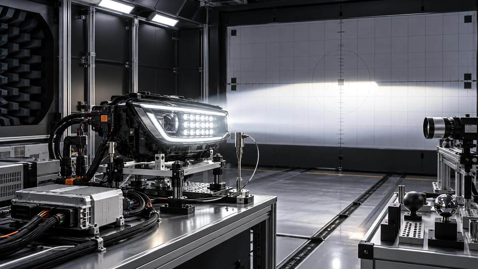
ASPICE for smart optical systems is not demonstrated by a polished process description alone. The assessment must show that every important decision can be followed from an intended vehicle function to implemented hardware and software, then to verification results and controlled changes. For matrix LED headlamps, camera-based lighting functions, photoelectric sensor switches, and related body-domain features, this traceability must cover both digital behavior and physical optical output.
The central question is simple: can the development organization prove that the released system does what was specified, under the conditions for which it was intended, and that changes remain under control? A convincing answer requires connected evidence, not isolated documents. A requirement list without test linkage, an architecture diagram without allocation rationale, or a test report without configuration identity leaves a material gap.
Start with the feature boundary, not the component label
“Smart optical system” can describe very different development scopes. A matrix headlamp may contain LED drivers, optical modules, thermal controls, embedded software, communication interfaces, diagnostics, and perception-driven masking logic. An automatic light or wiper function may combine ambient-light sensing, rain detection, vehicle-network signals, calibration parameters, and body-control software. The ASPICE evidence needed depends on what the organization owns and what is supplied externally.
The first assessment task is to establish a clear system boundary. A supplier developing only an LED control unit should not claim responsibility for road-projection behavior that is defined and validated at vehicle level. Conversely, a supplier that provides a complete adaptive driving beam function cannot treat optical performance as an external integration issue merely because the lens and LEDs are purchased parts.
A useful scope statement identifies:
- the customer-visible functions and operating modes;
- system elements, including optics, electronics, software, sensors, mechanical interfaces, and network connections;
- allocated responsibilities between vehicle manufacturer, Tier 1 supplier, semiconductor provider, optical-module supplier, and software partner;
- assumptions about vehicle inputs, vehicle states, calibration, and environmental conditions;
- items that are reused, inherited, or developed specifically for the program.
This definition prevents a common failure: evidence exists, but it belongs to a different product boundary than the one being assessed.
Requirements must connect optical intent to technical behavior
Requirements engineering is often where smart optical projects become difficult. Stakeholders may start with broad statements such as “avoid dazzling other road users,” “provide adaptive illumination,” or “switch lights automatically.” Those are legitimate functional intentions, but they are not yet sufficient development requirements.
A requirement set needs to make behavior observable and testable. It should distinguish between system-level intent and the technical conditions needed to realize it. For example, an adaptive lighting function may need requirements for object or vehicle detection inputs, valid signal states, response behavior, degraded modes, fault indications, communication timing, thermal derating behavior, and the relationship between requested light distribution and the commanded LED segments.
Optical output cannot be separated from the control logic. A software requirement might command a certain pixel group to dim, while the delivered beam pattern depends on LED binning, driver tolerances, optical alignment, lens condition, temperature, and calibration data. The development record should therefore identify where each performance-relevant assumption is controlled. If an optical tolerance is managed by mechanical design, that dependency must remain visible in the requirement and verification chain.
Evidence that carries weight
Strong requirements evidence normally includes a managed set of stakeholder, system, and software requirements; unique identifiers; acceptance criteria; rationale for critical allocations; and bidirectional traceability. Bidirectional matters. It should be possible to start from a road-guidance or anti-glare function and find the implemented requirements and tests. It should also be possible to start from a software unit, parameter, or test case and explain which approved requirement justifies it.
Review records are equally important. They demonstrate that ambiguity, conflicts, missing boundary conditions, and unverifiable wording were addressed before downstream work relied on them. Merely recording “review completed” is weak evidence. The record should show what was reviewed, who had the necessary competence, what findings were raised, and how they were resolved.
Architecture evidence must explain the safety and performance path
In smart lighting and sensing functions, architectural diagrams are easy to create and easy to overvalue. An assessment should look beyond boxes and interfaces. The essential question is whether the architecture explains how the function works, what can fail, and how the system responds when assumptions are no longer true.
For a headlamp controller, the architecture may need to show the path from vehicle or perception input through communication handling, function logic, diagnostics, LED-driving control, and feedback or status reporting. For a sensor switch, it should show how sensor signals are filtered, qualified, calibrated, combined with vehicle state, and converted into an actuator request. Interfaces must include the meaning of data, validity handling, timing expectations, initialization behavior, and failure reactions, not just signal names.
Hardware-software interaction deserves particular attention. A software team may correctly implement a dimming command, yet the output can still be inconsistent if the driver interface, current feedback, thermal model, or calibration storage behavior is insufficiently specified. The architecture should allocate these responsibilities explicitly and demonstrate that the relevant disciplines reviewed the allocation.
Where the system includes externally sourced modules, the organization still needs an integration position. A supplier document or data sheet is not automatically an architectural argument. The project should define the interface constraints, required assumptions, acceptance evidence, and change-notification obligations for that module.
Verification must prove the claimed behavior at the right level
One of the most persistent mistakes in ASPICE preparation is treating software test completion as proof of product readiness. Software verification is necessary, but it does not by itself establish that an optical system performs correctly on a vehicle.
A meaningful verification strategy separates evidence by development level and connects each level to the requirement it can reasonably verify:
Test specifications should identify the requirement under test, preconditions, equipment or environment, test steps, expected result, pass or fail criteria, and configuration of the item tested. For optical features, configuration control may include software version, calibration data, electronic hardware revision, LED or optical-module variant, and relevant fixture or vehicle setup. Without that identity, a passing report may not demonstrate anything about the release candidate.
Negative testing has particular value. Consider invalid camera or vehicle input, a sensor signal that remains implausible, loss of communication, thermal limitations, corrupted calibration data, degraded LED segments, reset behavior, or recovery after a transient fault. The evidence should show that these cases were selected from requirements, architecture, risk analysis, or known interface conditions, rather than added after a test failure.
Calibration data and optical parameters need lifecycle control
Calibration is frequently treated as workshop data rather than a development artifact. That approach is risky for smart optical systems because calibration may influence activation thresholds, sensor interpretation, projection alignment, dimming behavior, fault thresholds, or temperature compensation. A parameter set that changes behavior is part of the product configuration.
The development process should define who creates, reviews, approves, releases, and updates calibration data. It should also show how the data is linked to the applicable hardware and software versions, how incorrect or incompatible data is prevented from being used, and how changes are verified. The required depth depends on the function, but uncontrolled parameter changes can invalidate carefully executed verification.
The same principle applies to optical tolerances and manufacturing-related compensations. If a final end-of-line adjustment is needed to meet the intended output, its inputs, limits, result handling, and traceability need to be understood. It is not enough to state that production calibration exists; the development evidence must show its relationship to the specified function.
Change control reveals whether the process works under pressure
Projects rarely remain static. A new LED source, revised lens, altered driver integrated circuit, updated perception interface, or modified threshold can affect system behavior in ways that are not obvious from the change request title. ASPICE-oriented change management asks for more than approval history. It requires impact analysis and evidence that affected work products and verification activities were updated.
A credible change record links the request to impacted requirements, architecture elements, source code, test specifications, test results, released configurations, and open issues. The analysis should consider cross-domain effects. A mechanical adjustment can alter optical alignment; a thermal change can affect output derating; a revised network signal can change the behavior of an otherwise unchanged lighting algorithm.
Traceability tools can make these links easier to maintain, but tool ownership does not establish process capability. The important evidence is consistent use: approved baselines exist, links are current, exceptions are visible, and the release configuration can be reconstructed without relying on personal memory.
Assess the evidence as a chain, not a document collection
A focused sample-based review is usually more revealing than reading every artifact. Select a few representative functions, including one normal behavior, one degraded behavior, and one change made after a baseline. Follow each item through the lifecycle:
- Find the originating stakeholder or system need and its approved requirement.
- Check how the requirement is allocated to hardware, software, optics, or calibration.
- Review the architecture rationale and interface definition.
- Confirm implementation and integration evidence for the allocated elements.
- Trace to test specifications, results, anomalies, and closure decisions.
- Verify that the released configuration matches the evidence reviewed.
When this chain breaks, the gap is usually more informative than a missing template. A broken link may indicate unclear responsibility, unmanaged reuse, insufficient configuration management, or verification performed before requirements were stable. The corrective action should address that underlying condition rather than simply adding a traceability link before the assessment.
Do not confuse ASPICE evidence with regulatory or safety evidence
ASPICE evaluates the capability and consistency of development processes. It does not replace the separate work needed for functional safety, cybersecurity, electromagnetic compatibility, photometric performance, traffic compliance, or vehicle validation. These disciplines often interact in smart optical development, which is why their assumptions and outputs should be visible at interfaces.
For example, an anti-glare lighting function may have safety-related failure handling, optical performance criteria, software implementation requirements, and compliance constraints. Each discipline may maintain different evidence, but the development process must show who owns the interfaces and how conflicts are resolved. Treating these subjects as independent document packages often leaves untested gaps between them.
For exterior and vision-system programs, AEVS research on optical matrix algorithms, headlamp thermal behavior, and global traffic-compliance developments can help teams frame the technical context behind their evidence. The assessment itself, however, should remain anchored in the project’s controlled work products, defined scope, and demonstrated engineering decisions.
What to confirm before an assessment
Before presenting the project, confirm that the assessment scope reflects the actual delivered system; selected samples can be traced end to end; calibration and variant data are under configuration control; interface ownership is documented; unresolved anomalies have clear disposition; and test results identify the exact item tested. These checks expose substantive weaknesses early.
The strongest ASPICE position for a smart optical system is not a large repository of documents. It is a coherent development story that can withstand detailed questioning: why the function was specified this way, how it was allocated, how its behavior was verified, what changed, and why the released result remains valid.