
Industry Portal
Related News
- 00
0000-00
Precision Forging for Aluminum Wheels: Alloy Selection and Fatigue Performance - 00
0000-00
NEV Industry Standards in China: Which Battery Safety Tests Are Required? - 00
0000-00
Automotive Exterior Lighting Systems: Lamp Types, Functions, and Placement - 00
0000-00
Choosing an Electric SUV Sunroof: Key Fit, Safety, and Weather-Sealing Factors - 00
0000-00
Pop-Up Automotive Sunroof Systems: Key Design Factors for Vehicle Integration
How to Specify Low-Pressure Casting Parts for Leak-Tight Automotive Housings
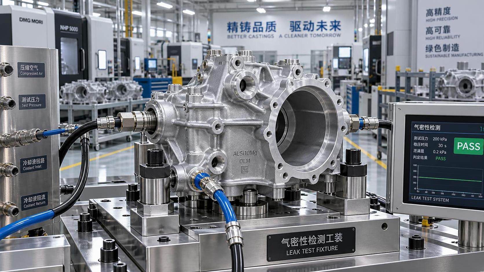
Leak-tightness is a casting-system requirement, not a single drawing callout
A low-pressure cast housing can meet nominal dimensions, alloy chemistry, and mechanical-property requirements yet still fail in service because its pressure boundary contains interconnected porosity, oxide films, shrinkage cavities, or machining-opened defects. For automotive housings that retain air, coolant, oil, dielectric fluid, or sealed electronic environments, leak performance must therefore be specified as the combined result of part geometry, alloy condition, filling behavior, feeding design, machining strategy, and test method.
The most important early decision is to define what “leak-tight” means in the actual vehicle system. A housing for a dry LED lamp cavity, a cooled power-electronics enclosure, and an oil-containing drive-unit cover do not have the same allowable leakage, test medium, pressure differential, thermal exposure, or failure consequence. A generic statement such as “100% leak tested” leaves too much open to interpretation. It may result in a casting process optimized for passing an end-of-line test rather than for maintaining pressure integrity after machining, coating, assembly loading, and thermal cycling.
Start with the pressure boundary, not the whole casting
The drawing should clearly identify pressure-retaining surfaces and separate them from noncritical external geometry. This distinction guides both casting design and inspection effort. A pressure boundary includes walls, bosses, gasket lands, threaded ports, internal passages, sealing grooves, and machined interfaces exposed to the contained medium. Features outside that boundary may tolerate surface discontinuities or local porosity that would be unacceptable near a coolant channel or threaded plug.
Critical zones should be shown on the 3D model and drawing rather than described only in notes. The supplier needs to know where porosity is prohibited, where limited isolated porosity may be acceptable, and where post-machining exposure of pores creates a functional risk. A useful requirement distinguishes among:
- the wetted or pressurized volume;
- the sealing land and gasket compression zone;
- machined holes, threads, and ports communicating with the pressure volume;
- high-stress regions where cracking could later create a leakage path;
- cosmetic or non-pressure exterior surfaces.
This zoning is especially important in complex aluminum housings. A local casting discontinuity that is harmless beneath an exterior rib may become critical if a later machining operation shortens the remaining wall thickness between a pore cluster and an internal fluid passage.
Wall thickness controls feeding and defect risk
Low-pressure casting is well suited to aluminum alloy components requiring controlled filling and good surface quality, but it does not eliminate the solidification challenges created by uneven section thickness. The process fills a die from below under controlled pressure. This can reduce turbulence compared with less controlled filling methods, but soundness still depends on directional solidification and adequate feeding as metal contracts.
The highest leakage risk commonly appears where thick sections meet thinner walls, at isolated heavy bosses, around flange transitions, and near blind pockets that become local hot spots. These areas solidify later than surrounding material. If they cannot be fed effectively, shrinkage porosity can form. A pressure test may not reveal every shrinkage region in the as-cast condition, while later machining can open a path to the surface.
Specify a target wall-thickness range and identify zones where abrupt transition is prohibited. The exact permissible variation depends on alloy, casting size, die design, and functional requirements, so a universal numerical limit is not appropriate. The engineering principle is more important: avoid large isolated masses, use gradual transitions, core out nonfunctional thickness where possible, and distribute stiffening through ribs rather than through bulky intersections.
Ribs require particular attention. A rib that is too thick relative to its adjoining wall can feed a local hot spot instead of reinforcing the structure efficiently. Rib roots can also become locations where filling, solidification, and machining requirements conflict. The design review should assess rib thickness, root radius, junction geometry, and proximity to fluid passages together—not as independent features.
Alloy selection must account for castability after downstream operations
An alloy should not be selected solely for tensile strength or corrosion resistance. Its response to low-pressure casting, heat treatment, machining, welding if applicable, and service temperature determines whether it can support a reliable leak boundary. Aluminum-silicon casting alloys are widely used because they offer fluidity and castability, but composition and heat-treatment condition affect elongation, thermal stability, machinability, and susceptibility to certain defect mechanisms.
The specification should state the applicable alloy standard or an unambiguous alloy designation, the permitted chemical-composition range where necessary, and the required delivery condition. If mechanical properties are required, define the test location and sampling basis. Coupon results alone may not represent the soundness of the thickest or most critical region of a complex housing.
For housings exposed to coolant, electrolyte contamination, road salt, or dissimilar-metal interfaces, material selection also needs to be tied to the corrosion-protection system. Conversion coating, paint, anodic treatment, impregnation, or sealing treatments can influence corrosion behavior and leak performance. These treatments should not be used to mask an inadequately sound casting unless their use is intentionally validated as part of the design solution.
Porosity requirements need a functional definition
“No porosity” is rarely a practical production requirement for a cast aluminum component. More importantly, it does not describe the defect condition that causes leakage. Isolated internal pores may have no functional effect; interconnected pores, oxide-film-related bifilms, shrinkage networks, and pores exposed by machining are more consequential because they can create a continuous pathway across the pressure wall.
A robust specification defines porosity in terms of location, size, connectivity risk, and inspection method. It may identify critical zones that require radiographic examination, computed tomography during development, metallographic sectioning, or process qualification evidence. The selected method should be matched to the failure mode:
- Radiography is useful for identifying internal volumetric discontinuities and comparing repeatability across production lots, but interpretation depends on wall thickness, geometry, and agreed acceptance criteria.
- Computed tomography offers more detailed three-dimensional information during design validation and root-cause analysis. It is less suited to routine inspection of every large-volume part unless cycle time and cost are justified.
- Metallographic sectioning can reveal local microstructure, oxide films, and fine porosity, but it is destructive and only samples defined locations.
- Pressure or leak testing verifies the functional condition of the finished pressure boundary, but it does not reveal all latent defects that could be opened by later operations or service loads.
Acceptance criteria should not simply borrow a radiographic grade from an unrelated component. A wheel, a structural bracket, and a sealed electronic housing can have different critical zones and different relationships between internal discontinuities and functional failure. The inspection plan should be based on the housing’s actual pressure path and machining map.
Machining allowance can either protect or expose the pressure wall
Machining is a frequent point at which latent casting defects become functional leaks. A generous machining allowance may seem conservative, but removing more material can bring a machined face closer to a porous region. Conversely, insufficient allowance can leave distorted or rough sealing faces that compromise gasket compression.
The drawing needs to establish the final minimum wall thickness after all machining operations, not only the nominal as-cast wall. This is particularly relevant around drilled passages, threaded bores, O-ring grooves, and gasket lands. Tolerance stack-up from casting location, fixture datum strategy, and machining position determines the actual remaining pressure-wall thickness.
Threaded ports deserve their own review. Thread cutting can intersect subsurface porosity, and thread-forming operations can locally load a thin boss. If a threaded connection seals through the thread itself, its leakage risk differs from a connection that seals on an O-ring, bonded washer, or face seal. Specify the sealing principle, thread standard, engagement length, local wall requirement, and any sealant restrictions. A thread that is structurally adequate may still be unsuitable as a fluid-tight interface.
For gasketed covers, flatness and surface texture cannot be treated as purely cosmetic machining requirements. They must be coordinated with gasket type, gasket compression range, bolt pattern, clamp-load distribution, and expected thermal movement. A highly polished surface is not automatically better; the required texture depends on the sealing material and the manufacturer’s application guidance.
Define the leak test as a reproducible measurement system
A leak requirement needs five linked elements: test medium, test pressure or vacuum condition, stabilization time, measurement duration, and allowable leak rate or pressure-decay limit. Omitting any of them produces inconsistent results between production sites or laboratories.
Air-decay testing is common because it is simple to automate, but a measured pressure drop is affected by part volume, temperature change, fixture expansion, and stabilization quality. It should not be specified only as “no pressure loss.” A large housing and a small housing with the same pressure-decay criterion may have very different actual leakage rates.
Helium-based methods can detect much smaller leakage paths and may be appropriate where ingress protection or very low fluid loss is essential. They also require controlled tracer-gas handling, calibrated equipment, stable fixture sealing, and a clear definition of whether the test measures gross leakage, total leakage, or localized leakage. Bubble testing can be useful for diagnostic confirmation, but it is generally less quantitative and more operator-dependent than a calibrated instrumented method.
The test condition should represent the finished part state. If leakage can be created by machining, inserts, plugs, welding, sealing compound, or coating, testing the raw casting alone is insufficient. Where the housing is later assembled with covers or interfaces that form the final pressure boundary, distinguish clearly between component-level and assembly-level test requirements.
Process controls belong in the sourcing specification when pressure integrity is critical
Part drawings define the product, but leak-tight performance also depends on process capability. For low-pressure casting parts, critical controls commonly include melt cleanliness, hydrogen management, die temperature control, filling-pressure profile, holding pressure, die coating condition, core quality, and heat-treatment discipline. These variables influence porosity and oxide inclusion risk even when dimensions remain within tolerance.
A supplier qualification package should therefore require more than an initial leak-test report. It should include evidence that the casting process is capable of consistently producing the defined pressure boundary. Depending on production volume and risk level, this may include control plans, traceability rules, process capability studies for critical machined dimensions, periodic destructive verification, radiographic audit frequency, and reaction plans when leak-test failures rise.
Lot traceability matters when a leak issue appears after delivery. The ability to link a component to casting date, melt batch, die cavity, heat-treatment load, machining cell, and leak-test record shortens containment and root-cause analysis. Without that chain, a supplier may be able to replace failed parts but not establish whether the issue is isolated, cavity-specific, alloy-related, or process-wide.
Validation should challenge the mechanism that can create a late leak
A housing that passes an ambient leak test may still fail after thermal cycling, vibration, clamp loading, corrosion exposure, or assembly stress. Validation should reflect the service conditions most likely to open a latent pathway. For an EV cooling enclosure, that may include temperature cycling with the intended coolant and pressure pulses. For an exterior lighting housing, the relevant concern may be moisture ingress, pressure equalization behavior, UV-exposed sealing interfaces, and thermal expansion around inserted components.
Where the housing includes dissimilar materials, such as steel inserts, polymer connectors, glass covers, or elastomeric seals, assess differential thermal expansion and interface loading. A sound aluminum casting cannot compensate for a poorly controlled joint design. The specification should define which interfaces are included in component validation and which are verified only at module level.
Dimensional requirements should also be linked to the functional sequence. A casting may satisfy as-cast tolerances yet move out of sealing-flatness requirements after heat treatment, machining, coating bake, or insert installation. The drawing datum scheme and inspection condition should reflect the stage at which the relevant function exists.
Common specification errors that create avoidable leakage disputes
One recurring error is demanding universal freedom from porosity without identifying functional zones or inspection methods. This creates an unmeasurable requirement and can push suppliers toward excessive screening without improving the actual pressure boundary.
Another is defining a leak rate but not the test volume, medium, temperature condition, fixture arrangement, or stabilization period. The same part can produce different results under different setups even if its physical leakage is unchanged.
A third is treating impregnation as an automatic correction. Vacuum impregnation can be a valid, controlled solution for certain porosity-related leakage paths, but it changes the manufacturing route and requires validation for fluid compatibility, thermal durability, machining sequence, and cleanliness. It should be explicitly permitted or prohibited, not introduced informally after a production problem.
Finally, do not assume that a successful prototype proves production readiness. Prototype tooling, low production rate, additional manual attention, and limited cavity use can produce different solidification conditions from serial manufacturing. Production-intent tooling and production-representative processing are necessary before a leak-tight requirement can be considered fully validated.
The strongest specification for low-pressure casting parts does not impose every conceivable inspection. It identifies the pressure boundary, protects it through geometry and machining rules, defines a reproducible functional leak test, and requires process evidence proportionate to the consequence of failure. That approach gives casting suppliers a technically clear target while reducing the risk that leak-tightness is discovered too late—after machining, module assembly, or vehicle-level validation.