
Industry Portal
Related News
- 00
0000-00
NEV Industry Standards in China: Which Battery Safety Tests Are Required? - 00
0000-00
Automotive Exterior Lighting Systems: Lamp Types, Functions, and Placement - 00
0000-00
Choosing an Electric SUV Sunroof: Key Fit, Safety, and Weather-Sealing Factors - 00
0000-00
Pop-Up Automotive Sunroof Systems: Key Design Factors for Vehicle Integration - 00
0000-00
Automotive Product Comparison Charts: How Buyers Can Compare Specs, Cost, and Fit
How to Specify Automotive Trim Parts for Durable Interior and Exterior Finishes
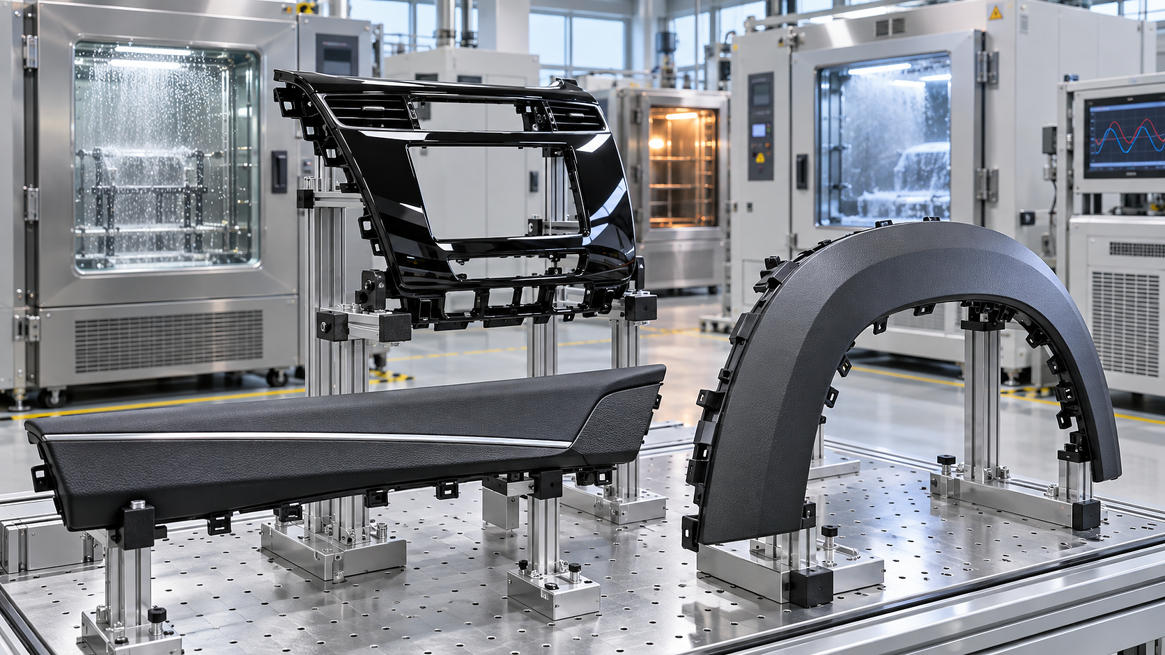
A durable trim specification begins by defining the part’s exposure, substrate, finish system, and failure threshold together. A piano-black appliqué on an instrument panel, a satin-painted door garnish, a wheel-arch cladding, and a lamp bezel can all look similar at launch, yet they age through very different mechanisms. A finish that survives routine cabin cleaning may fail under solar loading, road grit, de-icing chemicals, or repeated assembly contact. The drawing, material callout, grain reference, and validation plan must therefore describe the intended service environment rather than merely the desired appearance.
For automotive trim parts, the most expensive late changes often arise when a visible defect is treated as a cosmetic issue even though its cause is structural, thermal, chemical, or dimensional. Whitening around clips, gloss variation near ribs, paint cracking at an attachment point, and a widening gap at a curved joint each point to a different part of the specification. Separating those causes early produces a more durable finish and avoids asking a coating or texture to hide an unsuitable substrate or tool design.
Start with the exposure map, not the finish sample
Classify each visible surface by where it sits and what contacts it during vehicle life. Interior upper zones near the windshield receive concentrated heat and ultraviolet radiation. Door trim, console surfaces, and seat-adjacent garnishes encounter fingernails, rings, luggage, sunscreen, hand creams, disinfectants, and repeated wiping. Exterior components face ultraviolet exposure, water, road debris, detergents, airborne contaminants, fuel splash in some locations, and large temperature swings. Parts behind glazing or within lamp assemblies have their own thermal and optical constraints.
The exposure map should also identify local conditions rather than assigning one environment to the entire component. The outer face of a painted rocker moulding receives abrasion and impact, while the rear face may retain moisture and stress the attachment system. A sunroof surround may see cabin humidity on one side and roof-level heat on the other. A trim insert located beside a display or switchgear requires low reflectance and stable color, whereas a lower door appliqué may prioritize scuff resistance and repairability.
Electric vehicles deserve particular attention at heat-generating or airflow-sensitive interfaces. Lightweight exterior trim near battery cooling paths, wheel openings, underbody panels, and charging areas should be assessed for local heat, splash, vibration, and retained debris. These conditions do not automatically require a more expensive material, but they can invalidate a material choice based only on broad interior or exterior classifications.
Match material, process, and appearance
A material designation should state both the base resin or metal and the process route that creates the visible surface. Injection-moulded textured polypropylene, painted acrylonitrile butadiene styrene blends, polycarbonate-based high-gloss parts, stainless steel bright trim, and coated aluminum each have different limits for heat, scratch response, adhesion, and dimensional control. Calling out a color and gloss alone leaves too much room for substitutions that reproduce the launch sample but not its long-term behavior.
For moulded polymers, distinguish between a surface made in the tool and a surface created after moulding. Tool texture eliminates a coating interface, but its apparent depth, gloss, and color can shift with resin batch, pigment package, melt flow, mould temperature, and local packing. A coating can broaden appearance options and conceal some flow-related variation, yet it introduces adhesion, cure, edge coverage, and chip-resistance requirements. Film-laminated and foil-decorated parts add concerns around edge lifting, emboss stability, forming strain, and bond performance after heat and humidity exposure.
High-gloss black requires unusually explicit acceptance criteria. It reveals sink marks, weld lines, dust, read-through from ribs, handling scratches, and nonuniform polishing far more readily than grained or matte trim. A specification for this finish should define the viewing geometry, lighting condition, inspection distance, allowable defect type, protective-film requirements, and when that film is removed. Without those conditions, different inspections can produce conflicting pass or fail decisions on the same part.
Metallic and chrome-like appearances need similar discipline. Bright plated surfaces can expose edge geometry and substrate defects. Vacuum-metallized or painted metallic finishes may be sensitive to coating thickness, local curvature, and illumination direction. A visual standard should identify the approved master reference, orientation of the part during comparison, and whether adjacent parts are judged as an assembled set. Color tolerance on an isolated coupon does not ensure acceptable harmony between a fascia, grille, lamp garnish, and painted body panel.
Material decisions that change with location
Specify performance as a system
Scratch resistance is often reduced to one hardness value, which is rarely sufficient. Hard surfaces can resist a sharp point yet display obvious whitening, gloss loss, or brittle cracking after sliding abrasion. Softer surfaces may mark more easily but recover visually or blend the damage into a low-gloss texture. Define the likely contact mode: single-point mar, broad rubbing, repeated fingertip contact, cleaning-cloth abrasion, luggage scuffing, or grit-loaded abrasion. The test panel should use the production grain, coating build, cure condition, and color, because a smooth flat plaque frequently performs differently from a textured production part.
Gloss must be controlled with color and texture. A nominal gloss target without an agreed measurement angle, part orientation, and visual zone can hide unacceptable variation. Curved surfaces, deep textures, metallic flakes, and directional brushed effects can give instrument readings that do not match visual perception. Use numerical limits to control process drift, then retain an approved visual boundary sample for final appearance judgment. The boundary sample should represent the worst acceptable condition, not just the ideal master.
Thermal stability has two distinct aspects: the material must retain mechanical shape, and the finish must retain its appearance. Differential expansion between a polymer substrate, coating, decorative film, adhesive, or metal insert can create edge read-through, cracking, or delamination even when each material passes a standalone heat test. Long unsupported spans, thin walls beside thick bosses, sharp transitions, and localized attachment loads increase that risk. The part should be assessed after thermal cycling in its installed state when possible, because fixture constraints and mating components influence distortion.
Ultraviolet requirements should define the exposure orientation and the properties to be assessed afterward. Color shift, gloss loss, haze, surface chalking, adhesion, and impact behavior do not necessarily change at the same rate. Black unpainted exterior trim may retain apparent color while becoming brittle. A painted light-colored part may retain strength yet show unacceptable visual drift. For interior components, heat behind glazing can be as influential as ultraviolet energy, so the evaluation should avoid treating light exposure as an isolated variable.
Fit, attachment, and visible boundaries
A premium finish cannot compensate for inconsistent fit. Gap and flush targets should be assigned to visible interfaces, with clear datums and an installed measurement condition. Free-state dimensions are useful for mould control, but they do not establish the final appearance of a trim part held by clips, screws, adhesives, locator pins, or adjacent seals. Warpage can appear minor on a bench and become highly visible after assembly forces pull one corner into place.
Define which features establish location and which features retain the component. When clips are expected to locate as well as retain, normal variation in clip engagement can transfer into visible gap variation. A part with decorative coating or plating also needs protection around clip windows, weld tabs, and assembly contact zones. Coating damage at a hidden attachment point can propagate under moisture exposure and later emerge as an edge defect.
Assembly sequence matters for both finish and fit. A hard adjacent component can create permanent witness marks on a soft-touch surface. Protective films reduce transport and assembly damage but can introduce residue, static attraction of dust, or an unapproved gloss change if removed too late. Specify the permitted handling surfaces, packaging separation, film-removal stage, and repair policy. “No visible damage” is not a workable requirement unless the inspection condition and permitted corrective actions are defined.
Build validation around failure modes
Validation should link each test to a credible failure mechanism. Randomly accumulating tests produces paperwork without clarifying whether the part will age acceptably. A practical matrix connects exposure, material stack, critical feature, test method, preconditioning, post-test examination, and acceptance criteria. Post-test inspection should include dimensional condition and attachment integrity where relevant, not only surface appearance.
- Heat and humidity cycling: examine warpage, gap change, coating cracks, edge lifting, adhesive failure, and loss of clip retention after the part has returned to the defined inspection condition.
- Weathering exposure: compare protected and exposed areas for color, gloss, haze, chalking, and adhesion. Evaluate textured and high-gloss zones separately because visual failure thresholds differ.
- Scratch and abrasion: use representative contact materials and loads. Include both immediate marking and appearance after cleaning, since residue can temporarily exaggerate or conceal damage.
- Chemical resistance: test substances that are credible for the location, such as cleaning products, skin-contact residues, washer fluid, road-treatment residues, or fuel-related contaminants. Dwell time, temperature, and stress state materially affect the result.
- Assembly abuse: reproduce insertion, removal where serviceable, clip engagement, and neighboring-part contact. A finish that passes laboratory abrasion can still fail on the production line through a narrow guide feature or excessive insertion force.
Test samples need production-representative history. Early samples can be useful for screening, but hand-applied coatings, prototype tools, nonproduction curing, or temporary adhesives should not be used to close final durability requirements. If a process change alters resin source, pigment, coating chemistry, decorative film, mould texture, cure profile, or attachment material, assess whether the changed element affects the original failure mode. A color-matched substitute is not automatically performance-equivalent.
Control the specification package and supplier handoff
The release package should prevent ambiguity at the point where styling intent becomes a controlled production part. Include the material and finish stack, approved color and texture references, visible-surface zones, gloss limits where meaningful, dimensional datums, gap and flush criteria, attachment definition, environmental exposures, test methods, inspection conditions, packaging constraints, and change-notification expectations. Referencing a generic “approved sample” without version control invites mismatch when the sample ages, is damaged, or is interpreted under different lighting.
Request evidence that the proposed process can hold the specified surface consistently across cavities, production shifts, and expected lot variation. For moulded parts, review gate location, weld-line position, shrink assumptions, and the relationship between rib geometry and the Class A surface. For coated parts, examine surface preparation, coating thickness control, cure verification, and masking edges. For decorated parts, review forming strain, adhesive coverage, edge treatment, and how the decoration aligns to moulded features.
Cosmetic acceptance needs an escalation path for borderline conditions. Establish who owns the visual standard, how photos are captured, whether assembled appearance overrides isolated-part appearance, and how deviation samples are retained. This is especially important for components that sit beside painted panels, displays, lamps, or other high-visibility trim, where a small mismatch may become obvious only in the full vehicle environment.
The strongest automotive trim specification is specific about the conditions that create failure while leaving room for process innovation. It defines the visible result, the material system that supports it, the interfaces that can disturb it, and the evidence required after realistic exposure. That level of definition makes durable interior and exterior finishes repeatable rather than dependent on a favorable first sample.